PRESENTATION
The digital network was designed to accommodate traffic and the crossing of one to eight
locomotives.
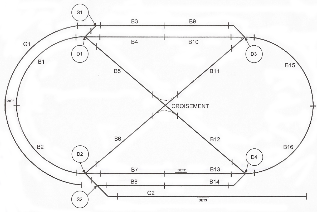
It is divided into 16 blocks: B1 to B16 and contains 2 sidings G1 G2.
This facility has:
- 13 "decoders K83" that control electro-magnetic 44 reacted upon by:
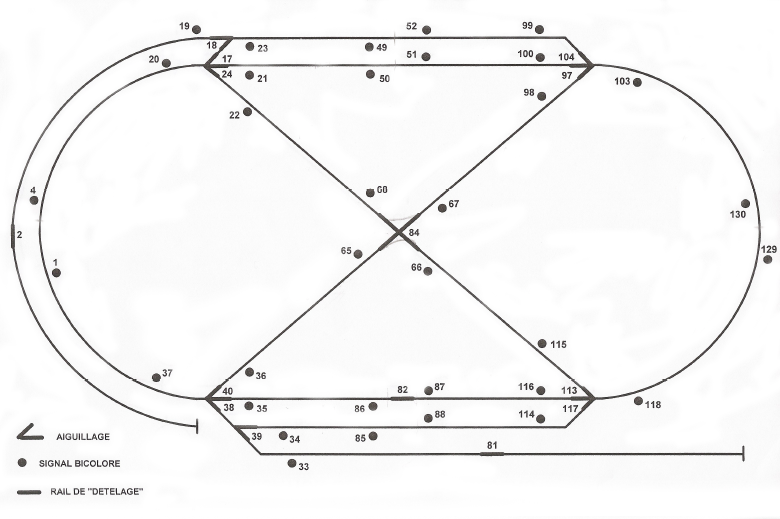
- 34 bicolor signals
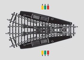
- 2 single switches
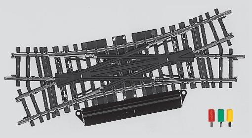
- 4 double switches
- 1 crossroad
- 3 uncoupling rails
- 3 decoders S88 with 39 sensors
LOCOMOTIVES
There are 8 locomotives with addresses: 10, 20, 30, 40, 50, 60, 70, 80
ELECTRO-MAGNETICS DEVICES
Bicolor signales
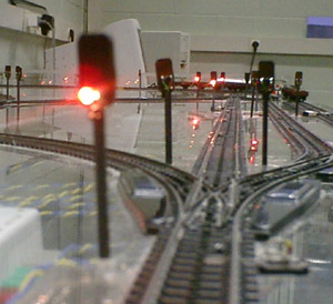 |
They are placed to the left in the direction of travel of the train.
All signals are wired so that the code 33 lamp lights green, 34 red.
The signals adresses are: 1, 4, 19, 20, 21, 22, 23, 33,
34, 35, 36, 37, 49, 50, 51, 52, 65, 66, 67, 68, 85, 86, 87, 88, 98, 99, 100, 103, 114, 115, 116,
118, 129, 130.
|
Single switches
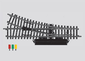 |
They are placed at the entrance of each of the two sidings.
S1, S2 referencing these two devices.
S1 to address electro-magnetic 18.
- The value 33 is associated with the position fork (no access to the siding).
- The value 34 is associated with the straight position (access to the siding).
S2 to address electro-magnetic: 39.
- The value 33 is associated with the straight position (access to the siding).
- The value 34 is associated with the position fork (no access to the siding).
|
Double switches
 |
A double switch is considered as the combination of two magnetic devices and
occupy two out of a "decoder K83. Accordingly, it will be assigned two addresses.
This pair of addresses can involve combinations of four values: 33-33, 33-34, 34-33, 34-34,
A double switch may take only three positions: Right, All Right, Left.
|
One of the four combinations will be invalid and generating derailments.
D1, D2, D3 and D4 refer to the double switches.
D1 is associated to addresses: 17 & 24
- The position to the left direction of travel of the train is obtained by combining:
Code position 34 for 17 / Code position 34 for 24
- The position straight direction of travel of the train is obtained by combining:
Code position 33 for 17 / Code position 34 for 24
- The position on the right direction of travel of the train is obtained by combining:
Code position 33 for 17 / Code position 33 for 24
- The invalid combination is:
Code position 34 for 17 / Code position 33 for 24
D2 is associated to addresses: 40 & 38
- The positions are deduced from the above by replacing 17 by 40 and 24 by 38
D3 is associated to addresses: 97 & 104
- The positions are deduced from the above by replacing 17 by 97 and 24 by 104
D4 is associated to addresses: 117 & 113
- The positions are deduced from the above by replacing 17 by 117 and 24 by 113
Crossroad
 |
The crossroad is associated to address: 84
The position code 33 is associated with cross (B5-B12 / B6-B11)
The position code 34 is associated with the bifurcation (B5-B11 / B6-B12)
|
Uncoupling rails
They are implanted to allow the implementation of such mechanisms
producers / consumers.
DET1 is associated with address: 2
DET2 is associated with address: 82
DET3 is associated with address: 81
For each of these three tracks, the code activates uncoupling position is 34, 33 disables it.
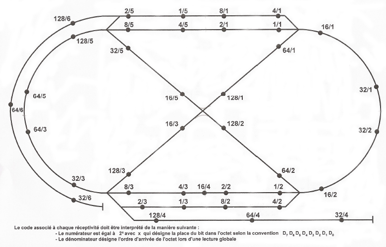
SENSORS
They were placed to make 16 blocks in the network. There are
three control points in each of the two sidings.
The position of each sensor and an identification code is provided below.
The identification code includes a numerator and a denominator.
The numerator is equal to 2x where x designates the place of the bit in the byte under the agreement:
D7D6D5D4D3D2D1D0
The denominator defines the order of arrival of the byte at an overall reading.
Recommended use:
- Each block has a sensor input and a sensor output.
- A medium speed, so that the stopping distance is sufficient (if required), the presence of a train on a block should be detected with the sensor input.
|

